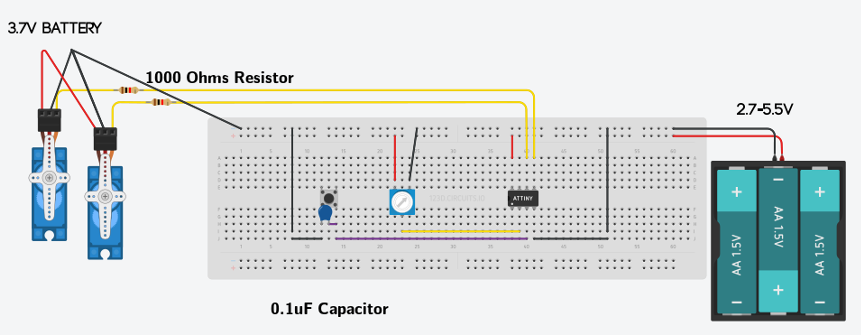
Control to servos with AVR Attiny85 microcontroller.
Back
Attiny85 Servos with C
Posted: 10-14-2017

Language: C
//      Attiny85 AVR Microcontroller
// C program for controlling 2 servos using a potentiometer and button.
// Author: Trigat

// I'm new to Attiny85 registers so this code will not be perfect
// and may need some tweaking.

// Put potentiometer on a pin such as PB3
// Put push button on a pin such as PB4
// Put servo on PB0 for OCR0A
// Put servo on PB1 for OCR0B

#define F_CPU 1000000UL // for 1Mhz Attiny85
#include <avr/io.h>
#include <util/delay.h>
#include <avr/interrupt.h>
#include <inttypes.h>

// Predefined Servo position values for OCR0A
// You need to fine tune this for different servos.
// Servo 1
#define SERVO1_ONE 8  // servo position
#define SERVO1_TWO 12
#define SERVO1_THREE 16
#define SERVO1_FOUR 19
#define SERVO1_FIVE 23
#define SERVO1_SIX 28
#define SERVO1_SEVEN 31

// Servo 2
#define SERVO2_ONE 15  // servo position
#define SERVO2_TWO 18
#define SERVO2_THREE 20
#define SERVO2_FOUR 22
#define SERVO2_FIVE 24
#define SERVO2_SIX 27
#define SERVO2_SEVEN 30

// used for button
uint8_t position = 1;

int main(void)
{
	// set potentiometer as input, other pins as output
	DDRB = 0b00111;  // Example: 0b10111 would be pin 3.  0b11011 would be pin 2.

	// Enable internal pull-up resistor on PB3(potentiometer) and PB4
    // and set others low
	PORTB = 0b11000;  // PB3 and PB4 set high

	// Mode 3 - Fast PWM
	TCCR0A |= (1<<WGM01) | (1<<WGM00);

	// Set OC0A/OC0B at BOTTOM (non-inverting mode)
	// Clear OC0A/OC0B on Compare Match
    // *** This may need to be adjusted ****
	TCCR0A |= (1<<COM0A1)|(1<<COM0B1); // (1<<COM0B1) controlls pin1
                                       // (1<<COM0A1) controlls pin0
	// Set prescaler to 64
	// 1 MHz / 64*256 = 61 Hz PWM frequency
	TCCR0B |= (1<<CS01) | (1<<CS00);

	// Start with the servo in center position
	OCR0A = SERVO1_THREE;
	OCR0B = SERVO2_FOUR;

    unsigned int adc_value; // Variable to hold ADC result

    ADCSRA = (1 << ADEN) | (1 << ADPS2) | (1 << ADPS0);
    // ADEN turns on ADC
    // ADPS2 and ADPS0 set to make division factor 32
    ADMUX = PINB3; // ADC input channel set to Pin3 (potentiometer pin)

    while (1)
    {
		// For potentiometer (servo 1)
        ADCSRA |= (1 << ADSC); // Start conversion
        while (ADCSRA & (1 << ADSC)); // Wait for conversion to complete
        adc_value = ADCW; // Store ADC value

        if (adc_value > 880 && adc_value < 1023)
        {
            OCR0A = SERVO1_ONE;
        }
        else if (adc_value > 680 && adc_value < 880)
        {
            OCR0A = SERVO1_TWO;
        }
        else if (adc_value > 570 && adc_value < 680)
        {
            OCR0A = SERVO1_THREE;
        }
        else if (adc_value > 450 && adc_value < 570)
        {
            OCR0A = SERVO1_FOUR;
        }
        else if (adc_value > 310 && adc_value < 450)
        {
            OCR0A = SERVO1_FIVE;
        }
        else if (adc_value > 200 && adc_value < 310)
        {
            OCR0A = SERVO1_SIX;
        }
        else if (adc_value < 100)
        {
			OCR0A = SERVO1_SEVEN;
        }

        // For button press (servo 2)
	    if (bit_is_clear(PINB, 4))
        {
	    	switch(position)
	    	{
                    // delay makes servo run smoother
	    		case 0:
	    			OCR0B = SERVO2_ONE;
	    			_delay_ms(600);
		    		break;
		    	case 1:
		    		OCR0B = SERVO2_TWO;
		    		_delay_ms(600);
		    		break;
		    	case 2:
		    		OCR0B = SERVO2_THREE;
		    		_delay_ms(600);
		    		break;
		    	case 3:
		    		OCR0B = SERVO2_FOUR;
		    		_delay_ms(600);
		    		break;
		    	case 4:
		    		OCR0B = SERVO2_FIVE;
		    		_delay_ms(600);
		    		break;
		    	case 5:
		    		OCR0B = SERVO2_SIX;
		    		_delay_ms(600);
		    		break;
		    	case 6:
		    		OCR0B = SERVO2_SEVEN;
		    		_delay_ms(600);
		    		break;
		    	default:
		    		break;
	        }
		}
		position++;
		if(position == 7)
			position = 0;
    }
}